Safety Integrity Level (SIL): Functional Safety in Accordance With IEC 62061
May 17, 2021
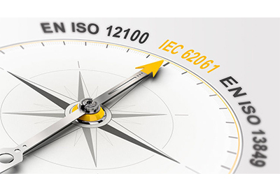
EN/IEC 62061 represents a sector-specific standard under IEC 61508. It describes the implementation of safety-related control systems on machinery and examines the overall lifecycle from the concept phase through to decommissioning.
Revision of the IEC 62061 standard
Mid February 2021 the new edition of IEC 62061 was published. The new edition is not only an update of the existing standard. For starter the standard is no longer limited to electrical system, but it can now be used with all kinds of technologies, for example for hydraulic or pneumatic systems.
Other important changes are:
- – changes to the methodology on how to define the required SIL-level.
- – the need to draft a Safety Requirements Specification
- – the possibility to use equipment designed according to other standards
- – more detail on Safety Related Application Software
Important information: The new edition of IEC 62061 (edition 2021) has not yet been published as a harmonised EN standard under the Machinery Directive in the Official Journal of the EU. However, harmonisation is expected in the near future. The current harmonised EN 62061 version is from 2015.
Contents of IEC 62061
IEC 62061 addresses the issue of how reliable a safety control system has to be. In this case the estimation is based on a hybrid method, a combination of a matrix and a quantative approach. It also deals with the validation of safety functions based on structural and statistical methods.
As with EN 13849-1, the objective is to establish the suitability of safety measures to reduce risks. Even with this standard, extensive calculations are required. You can significantly reduce the work involved with our software PAScal Safety Calculator.
What is determination of the required Safety Integrity like in accordance with IEC 62061?
For each risk requiring a safety control system, the risk must be estimated and the risk reduction coming from the control system (SIL) defined. The risk associated with the safety function is estimated in accordance with IEC 62061, considering the following parameters:
- • Severity of injury (Se)
- • Frequency and duration of exposure (Fr)
- • Probability of occurrence of a hazardous event (Pr)
- • Probability of avoiding or limiting harm (Av)
SIL classification in accordance with IEC 62061
Severity classification (Se)
| Impact | Severity (Se) |
|---|---|
| Irreversible: death, losing an eye or arm | 4 |
| Irreversible: broken limb(s), losing a finger(s) | 3 |
| Reversible: requiring attention from a medical practitioner | 2 |
| Reversible: requiring first aid | 1 |
Frequency and duration of exposure classification (Fr)
| Frequency of exposure | Duration (Fr) <= 10 min | Duration (Fr) > 10 min |
|---|---|---|
| ≥ 1 per h | 5 | 5 |
| < 1 per h to ≥ 1 per day | 4 | 5 |
| < 1 per day to ≥ 1 per 2 weeks | 3 | 4 |
| < 1 per 2 weeks to ≥ 1 per year | 2 | 3 |
| < 1 per year | 1 | 2 |
Probability classification (Pr)
| Probability of occurrence | Probability (Pr) |
|---|---|
| Very high | 5 |
| Likely | 4 |
| Possible | 3 |
| Rarely | 2 |
| Negligible | 1 |
Probability of avoiding or limiting harm classification (Av)
| Probability of avoiding or limiting harm | Avoiding and limiting (Av) |
|---|---|
| Impossible | 5 |
| Rarely | 3 |
| Probable | 1 |
How to design a safety function?
For every safety function the critical elements to perform the function must be identified, the so called subsystems. The selection or design of these subsystems must cater for a SIL which is equal or better than the required level. Next, also the combination of all of these subsystems must allow to reach the required SIL.
Every subsystem has to comply with:
- – Architectural constraints for hardware safety integrity
- – Probability of dangerous random hardware failures (PFH)
- – Systematic safety integrity requirements (requirements for avoiding failures and requirements for controlling systematic faults)
Architectural constraints of a subsystem
The SIL that is achieved by the subsystems impacted by the architecture of the control system and the “safe failure fraction” (SFF) or the level of diagnostics.
| Safe failure fraction (SFF) |
Hardware fault tolerance HFT 0 |
Hardware fault tolerance HFT 1 |
Hardware fault tolerance HFT 2 |
|---|---|---|---|
| < 60 % | Not permitted, unless well tried component | SIL 1 | SIL 2 |
| 60 % to < 90 % | SIL 1 | SIL 2 | SIL 3 |
| 90 % to < 99 % | SIL 2 | SIL 3 | SIL 3 |
| >= 99 % | SIL 3 | SIL 3 | SIL 3 |
HFT: Hardware fault tolerance
SFF: Safe failure fraction
Probability of dangerous random hardware failures of a subsystem
The probability of a dangerous failure of each subsystem is influenced by the used architecture, fault diagnostics and many more parameters. But every PFH value corresponds to a certain SIL level.
| SIL level in accordance with IEC 62061 | Average probability of a dangerous failure per hour (PFHD) [1/h] |
|---|---|
| SIL 3 | >= 10 E-8 to < 10 E-7 |
| SIL 2 | >= 10 E-7 to < 10 E-6 |
| SIL 1 | >= 10 E-6 to < 10 E-5 |

https://www.pilz.com/en-US/support/knowhow/law-standards-norms/functional-safety/en-iec-62061#news